All products
All category
5V 4 Channel Blue Color Relay Module
Product details of 5V 4 Channel Blue Color Relay ModuleChannel:4 channelColor:BlueContact Load:Low PowerDemo Board Type:OthersItem size:approx. 7.1 x 5.3 x 1.8cmNet weight:56.1gProtect Feature:SealedSize:MiniatureTheory:Voltage RelayUsage:General PurposeBrand Name:Noneis customized:NOMaterial:ABSDescriptions: 5V 4 Channel Blue Relay Module4 Channel Relay Module board is used to interface any Microcontroller with Electrical Appliances/Loads. Can also be used in driving high power motors.4-channel relay output modules, relay output contacts 250A 10A. Input IN1, IN2, IN3, IN4, the signal line LOW effective. VCC, GND power input, can relay a separate power supply relay power input of JD-VCC.What is a Relay?Arelayis an electrically operated switch. Many relays use an electromagnet to mechanically operate a switch, but other operating principles are also used, such as solid-state relays. Relays are used where it is necessary to control a circuit by a separate low-power signal, or where several circuits must be controlled by one signal.Relays work on electromagnetism, When the Relay coil is energized it acts like a magnet and changes the position of a switch. The circuit which powers the coil is completely isolated from the part which switches ON/OFF, This provides electrical isolation. This is the reason we can control a relay using 5V’s from an arduino and the other end of it could be running an 220 to 240V appliance, the 240V end is completely isolated from the 5V arduino circuitry.Channel: 4 channelRelay Operating Voltage: 5VTriode drive, increasing relay coilHigh impedance controller pinPull-down circuit for the avoidance of malfunctionPower supply indicator and Control indicatorlampPower supply and relay instructions, lit, the disconnect is off;The input signal, signal, common Terminal and start conducting;Specifications:Module can be controlled directly by Microcontroller (Raspberry Pi, Arduino, 8051, AVR, PIC, DSP, ARM, ARM, MSP430, TTL logic)Easy to install and fixOptically Isolated relays to protect your microcontroller from damage if the equipment being controlled failsfour screw holes, hole diameter 3.1mmrelay status indicator light, release status LED is offRelay Maximum output: DC 30V/10A, AC 250V/10ASize: 75mm (l) x 55mm (b) x 19.3mm (h)Weight: 58gPCB Color: BlueHow to connect:The connections to your Arduino (or microcontroller) side:VCC – supply voltage. 5V from my Arduino.IN1 – set to HIGH to set the relay to its “default” state, set to LOW to switch the relay to its alternate stateIN2 – same as IN1, but controls the second relay on the boardIN3 – same as IN1, but controls the second relay on the boardIN4 – same as IN1, but controls the second relay on the boardGND – groundApplication:Smart home controlIndustrial sectorFan/lighting control5-12 VDC automotive applicatiosupport all MCU control.the industrial sector;PLC control;smart home control;Package include:1 x 5v 4 Channel Relay ModuleSpecifications of 5V 4 Channel Blue Color Relay ModuleBrandNo BrandSKU220942533_BD-1167989626What’s in the box1x 4 Channel Wireless RF Remote Control Transmitter Receiver Module
5V 4 Channel Blue Color Relay Module
price
Secure
Checkout
Satisfaction
Guaranteed
Privacy
Protected
Details:
- Warrantyno
Product details of 5V 4 Channel Blue Color Relay Module
Channel:4 channel
Color:Blue
Contact Load:Low Power
Demo Board Type:Others
Item size:approx. 7.1 x 5.3 x 1.8cm
Net weight:56.1g
Protect Feature:Sealed
Size:Miniature
Theory:Voltage Relay
Usage:General Purpose
Brand Name:None
is customized:NO
Material:ABS
Descriptions: 5V 4 Channel Blue Relay Module
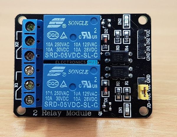
4 Channel Relay Module board is used to interface any Microcontroller with Electrical Appliances/Loads. Can also be used in driving high power motors.4-channel relay output modules, relay output contacts 250A 10A. Input IN1, IN2, IN3, IN4, the signal line LOW effective. VCC, GND power input, can relay a separate power supply relay power input of JD-VCC.
What is a Relay?
Arelayis an electrically operated switch. Many relays use an electromagnet to mechanically operate a switch, but other operating principles are also used, such as solid-state relays. Relays are used where it is necessary to control a circuit by a separate low-power signal, or where several circuits must be controlled by one signal.Relays work on electromagnetism, When the Relay coil is energized it acts like a magnet and changes the position of a switch. The circuit which powers the coil is completely isolated from the part which switches ON/OFF, This provides electrical isolation. This is the reason we can control a relay using 5V’s from an arduino and the other end of it could be running an 220 to 240V appliance, the 240V end is completely isolated from the 5V arduino circuitry.
Channel: 4 channelRelay Operating Voltage: 5VTriode drive, increasing relay coilHigh impedance controller pinPull-down circuit for the avoidance of malfunctionPower supply indicator and Control indicatorlampPower supply and relay instructions, lit, the disconnect is off;The input signal, signal, common Terminal and start conducting;
Specifications:
Module can be controlled directly by Microcontroller (Raspberry Pi, Arduino, 8051, AVR, PIC, DSP, ARM, ARM, MSP430, TTL logic)Easy to install and fixOptically Isolated relays to protect your microcontroller from damage if the equipment being controlled failsfour screw holes, hole diameter 3.1mmrelay status indicator light, release status LED is offRelay Maximum output: DC 30V/10A, AC 250V/10ASize: 75mm (l) x 55mm (b) x 19.3mm (h)Weight: 58gPCB Color: Blue
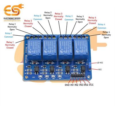
How to connect:
The connections to your Arduino (or microcontroller) side:VCC – supply voltage. 5V from my Arduino.IN1 – set to HIGH to set the relay to its “default” state, set to LOW to switch the relay to its alternate stateIN2 – same as IN1, but controls the second relay on the boardIN3 – same as IN1, but controls the second relay on the boardIN4 – same as IN1, but controls the second relay on the boardGND – ground
Application:
Smart home controlIndustrial sectorFan/lighting control5-12 VDC automotive applicatiosupport all MCU control.the industrial sector;PLC control;smart home control;
Package include:
1 x 5v 4 Channel Relay Module
Specifications of 5V 4 Channel Blue Color Relay Module
- BrandNo BrandSKU220942533_BD-1167989626
What’s in the box1x 4 Channel Wireless RF Remote Control Transmitter Receiver Module
related_products:
Hello! 👋🏼 What can we do for you?
01:58